Construction - Wear
I shall use a reduced size Movement wheel and it's pinion for these tests - why reduced size? Well it will give me a harder practice and also ensure I do not use them in the final clock! If I build the whole clock from this MDF laminated flooring, I have an unfortunate problem in that I will have to join two pieces together to make the 8" Minute wheel, as the planks are only 7" wide. So, for this test, the 48 tooth wheel will be made from 2 pieces. But first the pinion...
Opposite is the first set of drill holes for it. I attached 2 pieces of MDF together, holding them with 2 pins at the corners, before drilling out the centre, glued on the paper (spraying the glue on the paper, not the wood to make sure it did not enter the hole) and then drilled the connector holes. (Then poked through the middle hole up from the bottom - which is why it looks so ragged in the photo.)
The top piece will become the gear and the bottom one will represent another piece (crown wheel) on the arbor. The purpose in drilling both sets of holes at once is to make sure they will be accurately aligned on the arbor (assuming the drill is vertical!!). I think this is probable safer than drilling them separately once they are on the arbor.
I've also marked the sides of the pieces in preparation for marking one connector hole to ensure I always join them the same way.
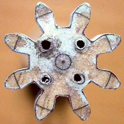
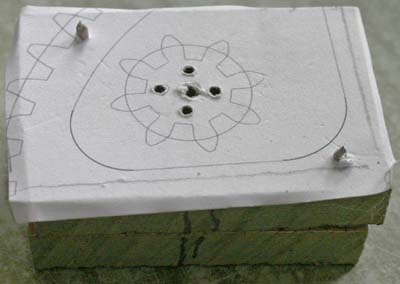
Here is my first cut on the pinion (4 times life size) after sanding it to the line. Pretty hopeless! I used a very fine blade to be able to go around the bends, as the bigger one sometimes burnt the wood, and it was slow and painful.
Even with a 100 watt bulb, I find it very hard to see well enough to cut accurately.
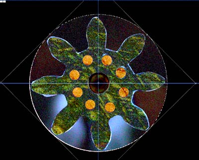
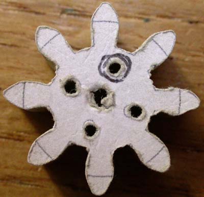
The imperfections are so much more obvious in this macro view.
I wonder if people using magnifying glasses to get things accurate?
I do not like the way the paper furs at the edges and one cannot easily see the line.
I must remember in real life that the wheels only revolve in one direction, so that the trailing edge of the teeth are not so critical.
I wonder if I print the template on transparent film and add some contrast - will that help?
lets see...
Well, that was a great idea and the second attempt is much better - shown opposite with template still present. One thin tooth (5 o'clock) and some red left at the corners. Had a bit of a problem glueing it on, but by leaving the glue for sometime before joining them seemed to work. However one can see that some 'saw dust' (greeny-blue - as this is MR MDF) managed to get between the wood and the template. But I had problems - basically the wood is so hard that I only have one blade that will cut nicely, but it does not like going around bends! So I left quite a bit of wood to sand away.
The Scroll Saw Sanding strips I brought are hopeless - wearing out very quickly and a couple of them broke. So I made my own, bending the sand paper around an old blade and they seem to work quite well, even just being held with paper clips!
I've thought of a good way to test the consistency of the teeth. Do the they look different? - difficult to tell with the naked eye, but take a photo of them (here is the second pinion) rotate a copy of the photo and show the difference between the two photos and then you can see how far the edges are out. You need Photoshop/Gimp/PaintShop to do this for you.
The blue bright edges to the teeth is the difference, and as you can see there is a big difference at the bottom of the two teeth at 9 o'clock. You see 8 connection holes because I have revolved one of the photos by 45 degrees (one tooths worth). Considering this is almost 4 times life size, it is not too bad. On my computer screen I can look at x20 magnification with no problem.
I shall use this technique before removing the template to check how I'm getting on! That should hopefully make the meshing tests quicker.
Next page
.