Construction - Wear Test
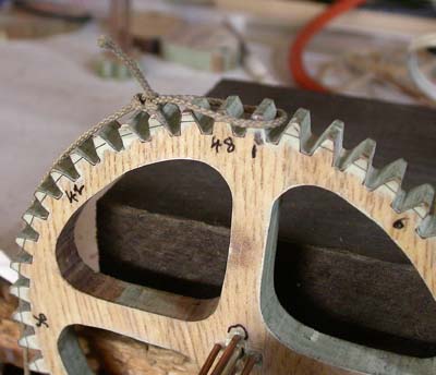
Cutting the wheel...
Well I almost feel like giving up! My Scroll saw
blades only last for 8 tooth's worth of cutting (it must be the two hard
surfaces which are blunting the blades), which was fine for the pinion,
but not the 48 tooth wheel! I had to use one blade to cut the
initial wedge, in more or less a straight line, and a finer one to cut
the bottom of the wedge out - very frustrating. Also I made a bad
assumption in that the pieces would glue together flat. Obviously
the moulding is designed to give a slight angle - so I have a bit of a
wonky wheel! I did however improve on the sanding strip - just
used one bulldog clip at the top, which was much better than a couple of
paperclips. I have to admit that I forgot to mark the two
pieces of wood to make lining up the connectors easy - guess it's old
age and I need to write down each step to make sure I do not miss one
out! Just as well I'm still experimenting! Computer printout
I forgot to mention that my printer does not produce a
perfect circle. I constructed one in Photoshop and then test
printed it. I had to scale the height by 0.99777, which was
equivalent to an error of 0.37mm, about 0.0156", in 8 inches.
To allow for small changes I used a resolution of 2400 pixels to the
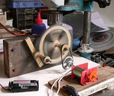
inch. The set up
|
| Here is my 'test' rig using a piece of wood held
down by the drill and an old motor and a bit of Lego. I placed a
couple of O-rings on the end of the arbors, just in case the wheels
wanted to move, but it was not necessary as they seemed quite happy
running in one position (despite the wobble of the non-flat large
wheel).
I cut out the spokes in a bit of a hurry and did not keep to the
line (same old problem!) - so I had to balance the wheel before running the test.
The 11cm diameter wheel weighted 2.6oz (74gm) before I cut and only
1oz (28gm) when I had finished cutting. I also used quite
coarse sand paper (150) for sanding the teeth, but in real life I must use
finer stuff. I did enjoy the blow tests - great to see the wheels free wheeling.
The small upright-ish piece of wood on the left allows me to
easily adjust the meshing of the pinion to the large wheel and is a
larger version than the ones I plan to use in the final clock for
all the arbors except the Minute wheel one.
|
 |
| I marked a tooth on each wheel, so that I will always mesh them
the same way. By taking photos at different shutter speeds I reckon the large
wheel is doing around 400 revs/min. In real life the large
wheel should be doing 8 revs/hr - so the clock is running at x3000
more than normal. In other words 2 hours of testing is
equivalent to about one year of normal running.
|
| Before starting the test I set up my tripod and camera so that I
can take before and after photos of the teeth wear. After a years worth of running, there was some
slight wear at this high speed - about 0.014" I reckon from measuring the photo (blown
up to 400%).
Opposite is a magnified view of the difference, which is visible
on the left side of the teeth. There are no visible markings
one either wheel - I reckon this stuff is so strong, nothing
is going to wear it down.
|
 |
|
|
So there is no point in testing the hardener with alternate teeth, BUT
it might reduce the friction and it will help to minimise moisture causing
expansion. I decreased the working distance between the teeth and then
carefully checked them and found 3 that were tight and needed further
sanding. I'm still not very happy with the clearance at the ends,
especially as I can not get the sanding strip into them. I fancy
that it may be a good idea to drill wee holes at the corners to ensure
there is no binding. |
|
|
| Firsts, I did a very simple experiment. Tied a
bowline knot in a 32" length of very thin string and hung it off the
teeth to see how well the wheel would turn when I let go (as shown
opposite) - just the string, no real weight at all.. First I tested it on the (brass) arbor as purchased,
doing a number of goes at each of the teeth 1, 13, 25 and 37.
The wheel revolved 36 teeth for the first 3 and 38 when starting at
37.
I then sanded the arbor with 600 wet&dry - yes, I know one should
use 1000 or 2000 grade, but I had not got any. Wow it caused more friction and the wheel would only revolve by
32 teeth.
I then used an old leather belt (because that is what the old
barbers did), pressed between my fingers to smooth the arbor - wow - then the wheel
would turn by 52 teeth. So smooth arbors are very important
and this seems a reasonable test to do when I build the clock for
real.
|
 |
| I then attached a 1gm washer to the string and
engaged the pinion (both now on the original non-polished arbors). For
the same set of starting positions, I got a movement of 36, 36, 33 &
36 teeth. I assume this is a test worth doing for real as it
is much more sensitive than moving the wheels by finger. Then I
painted all the teeth with hardener which reacts and uses moisture
as a catalyst for the hardening process. Once the reaction is
complete the resin is said to be water proof which will be a boon if
it does not effect the friction. I then had to wait 24
hours before redoing the tests, with the results of 37, 38, 33 & 37.
Great, so friction is slightly less. But how about hardening
the holes?
Well I rather dribbled too much of the hardener down the holes
and it has made things worse - movement down to 32 teeth. So I
gently reamed the holes by turning the drill bit by hand and then I
was up to 38 teeth. So it is all good news.
However this hardener is strong stuff, some of it dribbled onto
the flat surface and I could not remove it with a minute's worth of
hand sanding - so one must be very careful as it is applied. I
thought a pipe cleaner may be the best way to apply it to the holes.
|
|
|
|
|
Content Menu
|