Revisiting - Templates |
||||||||||||||||||||||||||||||||||
|
||||||||||||||||||||||||||||||||||
|
||||||||||||||||||||||||||||||||||
|
So off we go! I can start cutting the wood roughly to shape while
I try and solve the glue problem. |
||||||||||||||||||||||||||||||||||
Next page |
||||||||||||||||||||||||||||||||||
.
Revisiting - Templates
A test template of a grid was used to scale for printer errors. The re-scaling was done in PovRay as it is more accurate than Photoshop.
Well I managed to get a square accurately output on paper, but the scaling was not perfect. The closest I could get, although I could have spent more time scaling the PovRay output, was a length of 279.85mm instead of 280mm. But as all pieces that inter-mesh will be printed on the same sheet, it doesn't really matter that the wheels will be 0.9995% undersize! I wonder how people managed to produce dead accurate plans.
I'm still dithering about which directions the wheels should turn, so I will make two ratchets (and drum ends). Why two? Well you will remember that I want to overbore the inside of the holes (to reduce friction), so that the ratchet and minute wheel need to have their outer surfaces on the hard side of the flooring.
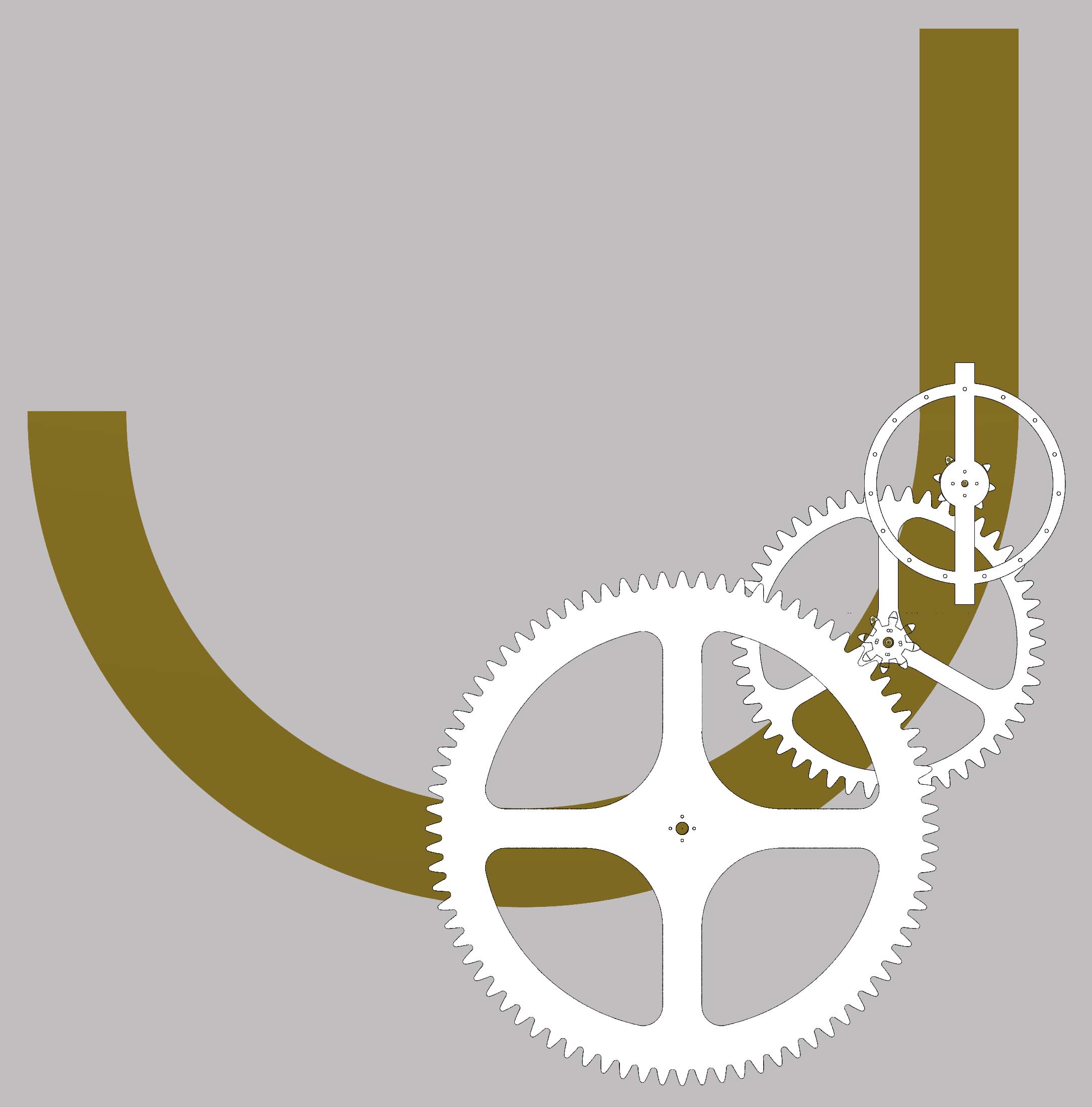
I have not paid a lot of attention to the frame or the verge - really because I need to experiment with these. So they will evolve after I have built and tested the wheels, but I include a tentative idea below.
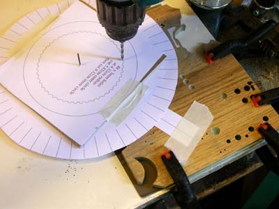
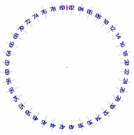
Before I completed the templates, I had one more test to try. Seeing if the idea of using a paper compass template to align drill holes really worked and also to try out a planetary Hour wheel.
All was very successful.
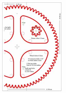
To see bigger template images (below), just click on them and then use the browser back button to return here. Those with red on them will be clear film and the others paper. Note that each template is contained within a square so that one can check the print is correct. Also where measurements are required, for instance when drilling holes at a certain radius, then a measure for that size is included (midline).
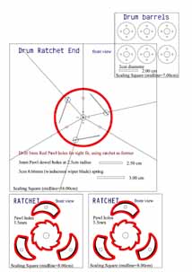
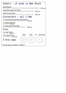
Drum & Ratchet
I'll also need two drum ends, but that is really simple.
The drum barrels do not really need a template!
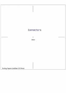
Connector template
I will need 4 of these - one for each joined component. They are just used to align the connectors, as specified on the wheel templates.
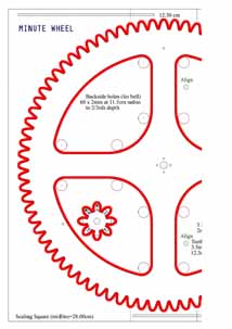
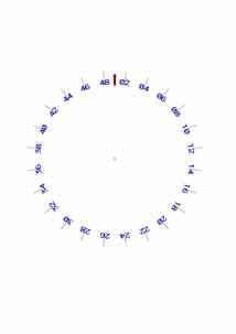
The Minute wheel
- has to be on two A4 sheets because of it's size and a couple of pinions in case I make a mistake as they are critical.
There is quite a lot of holes to drill in this piece. I will drill out the bottom of each of the 80 teeth to solve my problem of getting a clean edge at the bottom. It makes the teeth a 'little long in the tooth' (!) and it is not necessary to stop the pinion grounding - but it will help the cutting no end.
I shall drill the reverse side of the wheel with 60 pin holes in case I want to attach a bell mechanism.
To allow for different dials, I shall include 3 pins to hold it on with. If the dial then has 60 holes to align with these pins, it will be a simple matter to correct the shown time!
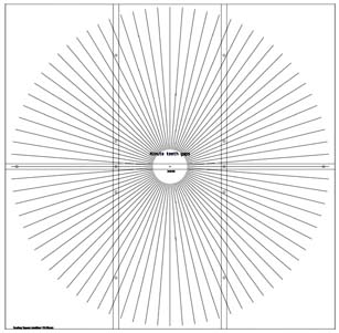
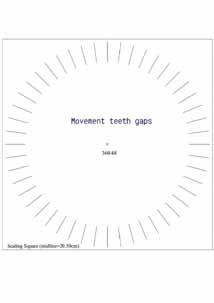
Here is the paper template for the 80 teeth - wonderful optical illusion! There are 6 A4 sheets - only one will be shown if you go for a large image.
I shall also have a paper template to identify the teeth - this will be temporary during testing. Also note that the teeth positions on the wheel and pinion are marked to ensure they will always be aligned the same way.
If I don't solve the glue problem, then this will be superimposed on the main template (as it will have to be removed when the clock is completed).
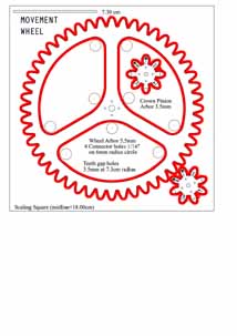
The Movement/3rd wheel.
All as one would expect.
Note that the pinion teeth are also numbered.
Have you noticed that I'm now doing for a 4-3-2 spoked system?
Opposite are the two paper templates.
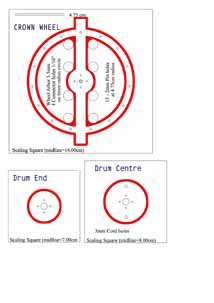
The Crown wheel
- with only 2 spokes - rather a fun idea I think.
Plus the remaining drum parts.
Ditto as above to drill the holes.
This template will not be correct if a different thickness of wood is used. Not shown are the end spacers, at the frame and end caps of each arbor, which will be cut from film.
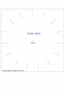
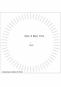
I've included this template for the Minute dial, the bell pins and it can also be used if I add a planetary hour wheel. I have not made a template for the Minute dial, as I'm still dithering! The Minute connector pins, which would drive the hour wheel, are at radius that is smaller then necessary to ensure that the hour wheel size will not be too big.
This my current thinking for the frame. The verge will hang from the upright and the leaverage pulley and weight from the left end of the circle.
The two moveable arbors will be placed on elliptical discs (so that is doesn't matter if they are at an angle, after adjustment).
So off we go! I can start cutting the wood roughly to shape while I try and solve the glue problem.
Next page
.