5 Leverage Pulley |
||||||||||
|
||||||||||
Next page |
||||||||||
5 Leverage Pulley
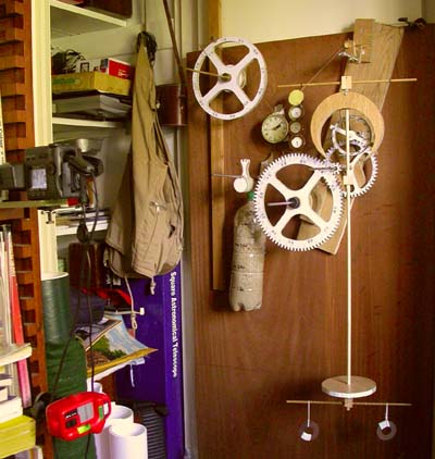
Time to move on and start on the pulley system. I cut a 23.2cm large grooved (to 21.9cms) pulley and a smaller 7.6cm diameter grooved (to 7.2cms) one (mounted behind, so the wire does not hang in front of the hour face) - giving me just over a x3 advantage. The assembly weighed in at 512gms, with no spokes and down to 286gms with spokes. The real great advantage of this system is that one can dial in any ratio one wants. I thought I would start with a 2 day clock as I still wanted to use the water bottle for weight and was therefore limited by how much it would hold. To up the weight I added some sand.
Another great advantage of this system is that I can accurately get the 1:12 ratio, so that the large pulley will show the hours, as there will be no slippage. All the clocks on the web never seem to have the hour and minute wheels aligned. I was obviously important not to cut the large pulley until I got the diameter of the drum decided. Then it was just a question of measuring the string length of 24 revolutions to deduce its size and then refining it by sanding the odd thou off.
However as the large pulley is connected to the drum, not the minute wheel, it will move each time one winds the clock up. Therefore a moveable hand/indicator must be attached, rather than marking the pulley itself.
I also brought some new fishing line as the monofilament one, I have been using up to now, stretches. The new 15lbs line is braided monofilament
and much thinner.
I also added a maintainer as I did not like the clock stopping when I
wind it up.
First to check I've not made any changes by introducing the pulley system. Run 1: I started off with a driving weight of 3005gms just to be on the safe side (as I did not know the extract friction of the pulley) as I needed at least 3 x 971 = 2913gms, but it seems too much as the pallets hit quite hard.
Half way through the test, I reduced the weight to 2913gms.
Not a great difference.
Run 2: Off with the stabilising disc behind the crown wheel and putting the verge weights at the bottom (as per photo above) on wee bits of string (easier to adjust). The maintainer shaft gets in the way of the weight, so that clock will only run for around 30 hours on one wind. I'll have to cure this when I add the elements to the frame.
I haven't the heart to stop this run as I'll probably never have a better one - so if I project the expected time using the first 6 hours as a guide, lets see how well it performs! So for instance, it is out by 20 seconds after 12 hours, less than 10 seconds at 24 hours. That is what I wrote after a day's running - but now... this is a humidity gauge, not a clock! How dramatic is this plot. Rewound the clock after 33 and 68 hours. The timer misbehaved and there are no readings between 57 and 67 hours.
The right hand plot is if I project the time for the 6 hours after the massive decrease in humidity at 48 hours. Remember the humidity is relative and inverted.
It is clear that the clock will never be accurate with these swings when the humidity changes. I just wonder if I can build in a Humidity Compensation Mechanism - but that is for another phase. I will now transfer the clock to the frame.
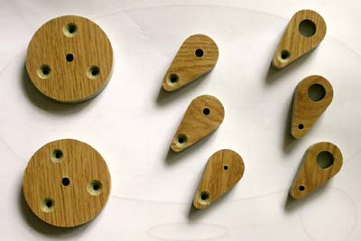
Here are the mounting plates. On the left the Pulley and Minute wheels plates.
In the middle the Maintainer, 3rd and Crown wheel arbors
And on the right the Verge plate and supports for the threaded adjusting rod.
Just for the record the arbor distances were 141.65, 92.60 and 200mm.
Next page